Within AirbotServices.com, all of our professionally built drones integrate a live telemetry link, outside of the main transmitter frequency band. We consider it to be a critical safety element that should be enforced in future European regulations for commercial drone activities. It is a must have. Why, you may ask ?
The current relative lack of reliability inherent to complex electronics and software modules composing a drone (although it may integrate redundancy) will sooner or later inevitably translates in "gremlins" during flight (a priori unexplained bugs) and/or eventually flyaways (uncontrolled drones).
Telemetry provides multiple safety functions:
-A safety functionality by monitoring real time critical elements that should be taken into account by the pilot (battery level typically)
-A safety functionality by sending real-time positionning (GPS) data on the ground station which can be used to find your drone that flew away;
-A debugging functionality by providing real-time to the ground the values of internal parameters (and therefore helps finding out why there is an uncontrollable behaviour);
-A logging functionality (Tlogs);
-An out-of-band communication outside the Radio transmitter band (it the 2.4ghz fails, the telemetry link might save you); not only to receive flight parameters on the ground but also to send commands.
433Mhz is the frequency of choice for telemetry as it provides the best range & penetration capacity through objects and walls versus higher frequencies (i.e. 900 Mhz or higher).
In Europe the maximum power allowed for using 433Mhz band, for other uses than amateur radio (for which an amateur radio license allows you to use hundreds or thousands of watts), is 10 milliwatts. This band is used for house alarm systems, remote controlled devices, etc.
Such a small power allowance makes it critical to optimize antenna designs on our drones, to maximize the range.
On the test bench : 4 different 433Mhz antenna models:
We will compare hereunder various 433Mhz antenna models, some are commercial stock models, others are DIY models based on best practices, among which excellent build advices provided on this blog:
http://diydrones.com/profiles/blogs/dipole-style-antenna-for-433mhz?id=705844%3ABlogPost%3A1674324
- 3DRobotics model:
The standard 3DR duck telemetry antenna such as shown here

is a 2Db compact sleeved dipole. It is sold with the 3DR telemetry kit.
- Nagoya 144/433 Mhz model :

Nagoya is famous for building excellent antennas. This is their telescope antenna, model NA-773.
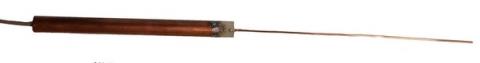
- AirbotServices' sleeved dipole model:
This is a 433Mhz model built by AirbotServices, designed by Joe ("Nampilot") as described in the blog link above,

It is made of 100% copper. Contrarily to simple dipoles where the two active elements have the same length and are fed in the middle (wich requires a balun to balance it to 50 ohms), this dipole consists of a longer top copper wire and a shorter copper tube which acts as a balun at the same time. The resulting antenna is not only perfectly tuned for 433Mhz, it is also 50ohms balanced without an additional balun.
A RG316 cable feeds this antenna.
- AirbotServices simple (standard dipole) model:

This is the classical dipole with servo wire and a RG316 feeding coax. We added a ferrite choke as a balun. The center is reinforced with balsa to maintain 90 degree angle between the active elements and the feeding coax.
Test method and results:
We use the RF explorer spectrum analyser as our test equipment. Rather than using its small integrated LCD screen, we used the windows PC client software, connected by USB to the RF explorer.
We intend to measure relative performance of antennas, not absolute gains nor range. Therefore we can skip anechoidal chambers and Faraday cages to make a much more simple relative test which will conclude on the impact of different antenna designs. As real drones do not fly in Faraday cages but in real noisy radio & EMI rich environments, the test signal was picked purely and simply in the ambiant "433Mhz band" signals, by selecting a constant stable peak signal. At the moment of the test, a particular constant peak signal was found at about 424-426Mhz. It is not an issue to measure aside the pure 433Mhz frequency as the telemetry device uses frequency hopping between 414Mhz and 454 Mhz.
So each tested antenna were screwed one after the other on RF explorer and we waited for a stabilization period. After which the signal DB levels were measured as follows:
The 3DR duck style Model:

The 3DR duck style antenna measures a -78Db signal level.
The Nagoya antenna model:

The Nagoya antenna measures a -69Db signal level.
The AirbotServices sleeved dipole model:

The AirbotServices sleeved dipole model measures a -69.5 Db signal level.
The AirbotServices standard dipole model:

The AirbotServices standard dipole model measures a -73.5 Db signal level.
Conclusions:
-The base 3DR duck model provides the least performance as we could expect, fixing an arbitrary base a reference level of -78Db
-Both the Nagoya and AirbotServices sleeved dipole provide the best performance, improving the measured signal by 9Db relatively to the base 3DR model.
-The standard dipole model lays in between with -73.5Db, which is still 5Db better than the 3DR model. It was also noticed during the measurements that this dipole is quite sensitive to polarization : a difference of 5Db could be measured by rotating the polarization. This sensitivity was not noticed that much with AirbotServices sleeved dipole.