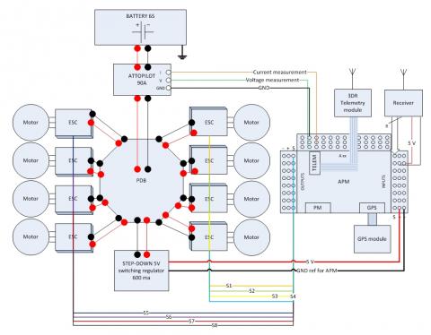

Figure 1: general wiring diagram for an 8 motors
& APM drone
Practical build blog: powering your APM drone
1. Foreword & Introduction:
I would like to introduce a build blog on a critical aspect of a drone’s assembly: how to power your drone & APM. The objective of such a build blog is to be practical. Wherever possible in this blog links will be provided to get the described components. This blog is merely a synthesis of gathered advices I received from many helpful people within this drone community (particular thanks to Randy, Bill, Forrest and many others who taught me lots and are still teaching me lots of stuff)
As a topic I chose “Powering the APM” as it is in my opinion one of the most critical aspect you should care for in assembling your drone. I’d probably be not too far from the truth if I said a majority of drone incidents & crashes are related to power issues or bad wiring/testing (brownouts, wiring mistakes, ground loops, wrong voltage/amps dimensioning, etc.).
The blog does target people at early stages of drone build’s learning, like the state I was in a few months ago. It was very hard to find all bits and pieces of information to get a global detailed picture. Let’s hope this blog can help others in their build.
This blog will be written in successive posts as it is a fairly long subject and my time is quite limited. It will also allow others to interact and add complementary input between my posts; to be enriched progressively.
2. Powering an APM Drone: Objectives and Constraints?
Cf. figure 1 above illustrates a general wiring diagram for powering a typical drone. It illustrates 8 motors and ESCs but would remain applicable for fewer motors (battery voltage would probably go down to 3S or 4S for quad motors).
First, what are the objectives ?
-As illustrated in figure 1, a first objective is to power ESCs and associated motors with a high power source in terms of amps/volts, able to sustain the maximum throttle consumption and voltage required by the motors and propellers configuration (with a margin is even better). A good way to dimension this for your own setup is to either measure real values on a test bench (not so practical because it implies you would already know what to do and what pieces to buy), or more practically to use an online tool which is not so bad to give rough estimates here : http://www.ecalc.ch/xcoptercalc.htm?ecalc&lang=en
Another good information source about motor testing is an excel sheet with test bench measurements done by Forrest. Forrest, if your read this, could you post your excel sheet please ? Thx.
The eCalc tool asks you to enter your number of motors, the all up weight of your model, the battery type, the ESC capacity in amps, the motor’s brand and model, propeller’s type and model. You then click on calculate and the tool displays at the bottom 5 results columns. The most interesting columns for our exercise are “Motor@maximum” and “Motor@Hover”, because it will give you the consumed amps at maximum and at hover, the voltage and throttle % to hover (ideally should be at 50%). If you are under dimensioned or over dimensioned (under optimized), the tool will display some warning messages. The tool allows you thus to check that all the parts are dimensioned correctly to function together. For example, assume the tool tells you that your hover power consumption is X. However your motor’s maximum power specification is Y. Verify that X < Y. If not change the motors or use smaller props or lower pitch props (same verifications to do with max amps, max volts, max RPM, etc).
I have used this tool to produce a table for a particular motor brand, RC tiger motors here: http://www.diydrones.com/group/arducopterusergroup/forum/topics/tiger-motors-propellers-combinations-for-an-heavy-lift-octocopter?xg_source=activity
-A second objective is to power all other components that are not part of the high power gear, namely APM and all other bits and pieces around it: a receiver, a telemetry unit, a GPS/compass module, etc. Optional servos that are require to power for gimbals for example ARE NOT low powered items; they CANNOT be powered through APM but must be powered directly from the high power source (via UBECs). As far as electronics is concerned, the objective is to feed a very stable and reliable power source at 5 volts (there may be other specific FPV/OSD components that require other voltages such as 12v or 7v but I exclude these components from this blog for now). This second objective seems apparently easy to reach but it is actually a very sensitive and tricky one as we will see in more details later.
Second, what are the constraints ?
We want to reach above described objectives within constraints:
-The power chains must be reliable and as light as possible (typically if we can use the main battery for everything, it will be lighter than if you need a separate battery for every component).
-There is better one main battery as the power source for everything (which avoids different ground references, avoids potential ground loops, makes your build lighter). So we have a constraint to split the power chains to different voltages/amps (main voltage for ESCs and motors, and 5V for APM and associated electronics). These LIPOs are power monsters people should be aware of: they are capable of delivering very high amperage (e.g.: more than 100 amps in my X8 drone application) at a set voltage between 3S (11.1V) and 6S (22.2V) for most drones. If you make the math, we speak here of order of magnitudes of between 1 to a few kilowatts of power!
There is a link you may consult about batteries common brands discussion here: http://www.diydrones.com/group/arducopterusergroup/forum/topics/6s-battery-comparison-on-some-most-common-brands-turnigy-zippy?xg_source=activity
-The main power source must feed high amps and high voltage to the ESCs+motors. We have a constraint to measure both amps and voltage fed to the whole drone as it is a critical piece of information you want to check continuously on your GCS (or goggles) while flying. It would be insane to fly without such real time information, as you do not want to let your copter fall out of the sky once your battery becomes empty.
An assembly constraint is thus to wire every bits and pieces in such a manner that your current and voltage sensors measure the TOTAL (SUM) of all amps consumption. If you use two batteries , do obviously not connect your sensors after one of the two batteries. Another classical mistake is to connect items pumping current and voltage from the sensors wires!
Avoid connecting items in such a way you create ground loops. Connect everything in a STAR topology, with the center of the star connected right after the current/voltage sensor on the high power leads/wires. As it is difficult to visualize your wiring in the practice, make a wiring diagram of your connections and check it out (like I did on figure 1 for example)!
As you will notice on figure 1, I kept a ground loop with the ground wire of the Attopilot module, but it is impossible to connect otherwise. It is one of the weak point of Attopilot sensor usage, unfortunately. Some posts have been done about this here : http://www.diydrones.com/forum/topics/attopilot-volt-current-sensor-significant-parasitic-ground
-At the same time the main power source must be derived to feed a set of sensitive electronics at 5 volts. APM has a constraint to be fed at a voltage between 4.6V minimum and 5.25V maximum. If you are below the minimum voltage, your APM will brownout. If you are above you will fry APM. However it is not so easy to get a stable 5V source as the load varies. Take a look at the picture below that illustrates how unstable an APM 5V power source could be (and there is even worse):

Figure 2 : Bad Vcc illustration
Figure 2 shows a 5V power source from a switching BEC regulator. The measured voltage on this BEC was 5.14V unconnected. We observe from this log picture that once connected the voltage immediately drops down to 4.9V which is not good. Further a strong variability of the voltage between 4.6V and 4.9V is observed. This brings the voltage close to the power limit of APM’s power requirements with a risk of brownout. We will see later in this blog how this problem was solved.
3. Tested solutions to fulfill powering objectives and constraints:
3.1-Battery solution:
For the main battery, I chose a dual battery setup to reduce total cost of ownership (and increase max amp capacity). In an objective to increase flight duration to the maximum I looked initially at high capacity batteries such as maxamp 12.000 mah or equivalent from other brands. In a 6S voltage these batteries are awfully expensive (sometimes more expensive than a complete 3DR RTF kit!). Therefore, I found best for me to use two smaller 6000mah batteries. It weighs the same or even less than a 12.000 mah battery, it costs a third or a fourth of the price if you get a turnigy nanotech or zippy brand. There comes a physical challenge to install multiple batteries on a drone without ruining your possibilities to attach a camera gimbal underneath, and without ruining your possibility to use a protective dome for electronics on top. So for my octoquad, I’ve custom cut a dual battery holder CF plate that screws on the center plate, providing two side platforms left/right to fix the two batteries (thx VulcanUAV for their help!):

It looks like this once assembled on the drone’s frame:

After choosing the battery , we need to think about how to wirre in a STAR TOPOLOGY.
I found the easiest way to do this was to use a power distribution board, like this:

I personally chose to use a 250 amps capacity power distribution board from VulcanUAV here : http://www.vulcanuav.com/accessories.html
It is much better and safer than using cable solutions, for example like this:

3.2-Power distribution board
I will now start to detail this power distribution board, based on figure3:

Figure 3 : Power distribution board placement assembly
Part 2:
Figure 3 shows the different elements you should have on your power distribution board. I have numbered them on the picture for easier reference.
-Fig3 n°1: Attopilot circuit. The attopilot is a small pcb circuit to measure current and voltage,

You can find it at sparkfun in the US, or here in Europe: http://www.buildyourowndrone.co.uk/AttoPilot-90A-Voltage-Current-Se...
The illustrated version is the 90 amps attopilot. There exists also a 180 amps version. In practice, the attopilot is made so that the current sensor pin (I pin on the attopilot board) outputs a voltage between 0 and 3.3V (3.3V would mean 90 amps are measured on the I pin). This I pin is connected to an APM A2 sensor pin (see figure 1). APM measures on a scale between 0 and 5V. This in fact gives a possibility to measure a maximum current of more than 90 amps, that is (5x90/3.3)=136 amps maximum.
136 amps is largely enough for most drones. Otherwise you have to take a 180A Attopilot version. Do not try to oversize your attopilot circuit because you would loose in measurement’s resolution (precision).
As you see on Fig3 n°1, I tried to keep the integration of the attopilot module between the main battery leads and the PDB as compact as possible. This means it was impossible to use shrink tube to wrap the Attopilot and connections, because the wires being so short do not allow you to solder and place at the same time a piece of shrink tube between Attopilot and PDB. How to solve this? Use Plastidip:
http://www.plastidip.co.uk/eStore/index.cfm?Plastidip_Junior_Can_25...

It is a liquid plastic/rubber material that you apply with a brush on your parts. You can also dip your whole circuit in it. After drying (it does dry fast), the coating really shrink tight on the covered element. It makes a really nice alternative to heat shrink.
Note that you can choose where to position the different elements around the PDB. I specifically positioned the two main battery leads with the attopilot circuit on a position corresponding to the back of the drone. This will avoid battery wiring to come in front of the cameras I will use.
It is a good practice to mark with a permanent marker every useful information on the different components. For example, indicate with an arrow where the front is, number all of your motors/ESCs, etc.
-Fig3 n°2: the switching regulator to feed APM. You need a switching regulator that will be robust and reliable and that provides a stable 5V to APM, even under load. APM uses a few hundreds milliamps at most, so you do not need to feed APM with a 3A or 5A power source.
There are different types of switching regulators. Not all are good for APM.
Initially, I tried these Polulu switching regulators which I DO NOT recommend because they produce a very unstable 5V voltage on APM. I tried two models, one with fixed 5V output and another one with adjustable output: polulu 2107, polulu 2103.

It is a pity because they would be extremely compact and have nice theoretical features : takes an input voltage between 7 V and 42 V and efficiently reduces it to 5 V while allowing for a maximum output current of 600 mA.
However the 5V result on APM is dangerous, as it provides a highly fluctuating voltage down to 4.6V (although the circuit was tuned to produce 5.14V unconnected):

Bad Vcc instability
Instead I found an even cheaper circuit that works much better. It is this one: 12W Step-Up/Step-Down Converter 3-35V Input, 1.2-30V Output (adjustable) with 2amps max at 5v.

A 2A (5V output) can be achieved without additional cooling, the efficiency is up to 90%, the switching frequency at 150kHz. The module is protected against short-circuit (10 seconds), but not against reverse polarity.
And best of all, it costs only about 7$ (5€) !
You can find it on ebay or here: http://www.lipoly.de/index.php?main_page=product_info&cPath=880...
It uses the Texas Instrument LM2596 switching regulator circuit. The data sheet can be found here:
http://www.ti.com/lit/ds/symlink/lm2596.pdf
And it produces the following excellent 5V stable results on APM, even under load (with 3DR telemetry, GPS module, Receiver module, two LEDs, a buzzer connected and fed by APM):

Excellent Vcc stability
This switching module is ready to use out of the box (which is not the case of the Polulu because you still need to solder a capacitor on it). You just need to solder the wires that will connect to the PDB on one side, and on the other side you solder the two wires that will go on APM.
You will notice in Fig3 n°2 that I twisted the two wires that will connect on APM and used a ferrite ring. You will also notice that I did not twist the last two inches or so of these wires that will connect on APM in order to have minimum vibrations transmissions to APM through the wires (when you twist the wires they become more rigid and they transmit more vibrations).
Part3 :
-Fig3 n°3 :
Number of all your ESCs with a permanent marker. Place them around the power distribution board before assembly. The order of the ESCs must match the motor positioning as defined in the wiki. It depends on your setup: a quad, a X8, a hexa, etc.
Also mark the spot on the power distribution board where the ESC will be connected to.
-Fig3 n°3bis:
To limit electromagnetic disturbances to the maximum, use as short as possible power leads between ESCs and PDB. Some people prefer to use bullet connectors between the ESCs and PDB . I prefer to solder them directly on PDB as this is a much more secured way to avoid bad connections or even disconnections in flight (vibrations do wear connectors)!
Define very carefully what the length of your ESCs power wire should be BEFORE cutting them. For example if you have a folding frame and you need to flip arms, maybe you would need a bit of wire slack.
In my case I decided to use the aluminum arms as heat radiators for the ESCs. Therefore I need to glue the flat face of the ESC (the face corresponding to the integrated aluminum plate) on the arms. That meant that I had to twist the power wires on 4 out of the 8 ESCs (see figure 3).
-Fig3 n°4:
You should use only 4mm bullet connectors (or bigger diameter) to connect your motors to the ESCs. Nowadays, most ESCs and motors are delivered by default with smaller bullet connectors. They are very dangerous to use when too short and too small as they really could disconnect in flight due to vibrations or by accident if a cable is pulled a bit too much. With 4mm, they are perfectly fine.
Also BEFORE you assemble your ESCs and motors, number each of the three ESC wires according to the corresponding motor number. I reuse the same numbers as defined in the wiki, depending on the frame type. Also use three different c olors that will match the same colors on the motor’s leads. How do you do this ?
Take each motor individually and its corresponding ESC (they will be marked with the same number). Then plus the motor to the ESC, connect the three signal wires of the ESC to a receiver on its throttle channel, which is normally channel 3 in Arducopter (the receiver will be powered by the red & black wires), power the ESC with the intended battery. Turn on the radio and give a bit of throttle to check the rotation direction. If it does not match the direction as defined in the wiki for this motor number for this type of frame, then swap two of the three ESC-Motor wires. Check again. Once you’ve got the intended rotation direction, mark each of the three ESC-Motor wire with an identical color.
Repeat the procedure for each motor. After that you will have everything that is needed to assemble your drone without risking a bad connection or a wrong ESC-Motor wiring.
-Fig3 n°5:
Number five shows one of the ESC’s signal wire. I have cut the red and black wires as they are not used in the wiring diagram shown in figure1. You should do the same and not connect the red and black wires of the ESCs to the APM output rail (see figure1). Not only it would be dangerous to do so electrically speaking, but it brings the additional advantage of having a tidier wiring with less wires.
Mark with a permanent marker on each of the ESC’s signal wire (orange wires on figure3) with the same number as the motor number they correspond to. Indeed if you forget to do so, once you will have assembled the center frame, you shall not know anymore which wire is which to connect on the 8 APM signal outputs.
-Fig3 n°6:
Also mark precisely what is the front of your drone. This is important to optimize your cables placement. For example, I know that I should position the two XT90 battery connectors at the back of my center plate. The placement of your cables depend on your particular frame and how you’d like to pass your cables though the frame plates up to APM. This is why marking the frame and PDB orientation is important.
Indicating where the front is is also important to place your motor/ESC numbers at the right place (as defined in the wiki depending on your particular frame type).